|


| | SID Series General Specifications 
| This series of push-on/pull-off connectors provides a reliable 15 KVDC high voltage connection for use in military and aerospace applications.
A unique interface sealing system allows these connectors to perform well under vibration, shock, altitude and temperature extremes. Mated SID assemblies also have good corona
characteristics.
SID assemblies are especially well suited for interconnecting high voltage system components. The excellent flexibility of the silicone cable makes system cable routing simple and reliable.
A variety of panel connectors are available as well as straight and right angle cable plug assemblies.
SID assemblies are widely used in: Interface cleaning High voltage connectors must always be cleaned prior to mating. The proper cleaning method is to wipe or spray the interface area with isopropyl alcohol and immediately blow an inert gas such as dry nitrogen over the interface area until dry. No other cleaning method should be attempted.
WARNING: These connectors should NEVER be handled, mated or unmated when voltage is applied. |     
|
Download PDF for all SID Series General Specifications |
SID Push-on/Pull-off cable assemblies and receptacles, Page 1 
SID - 15 KVDC Plug Cable Assemblies Single-Ended Straight Assembly | |
| | 
| Note: Stranded wire shown on single-ended assemblies is for factory testing and is not included in length dimension. 178-6076 SID Series Single Ended Straight Cable Assembly Wire Dia. 0.165 (4.1) 178-6075 SID Series Single Ended Straight Cable Assembly Wire Dia. 0.180 (4.5) Mating connector: All SID receptacles Mating method: Push-on/Pull-off | Double-Ended Straight assembly | |
| | 
| 178-6078 SID Series Double Ended Straight Cable Assembly Wire Dia. 0.165 (4.1)
178-6077 SID Series Double Ended Straight Cable Assembly Wire Dia. 0.180 (4.5)
Mating connector: All SID receptacles Mating method: Push-on/Pull-off | Single-Ended Right Angle Assembly | |
| | 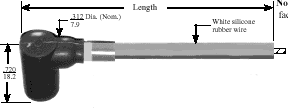
| 178-6080 SID Series Single Ended Right Angle Cable Assembly Wire Dia. 0.165 (4.1)
178-6079 SID Series Single Ended Right Angle Cable Assembly Wire Dia. 0.180 (4.5)
Mating connector: All SID receptacles Mating method: Push-on/Pull-off | Double-Ended Right Angle Assembly | |
| | 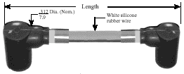
| 178-6082 SID Series Double Ended Right Angle Cable Assembly Wire Dia. 0.165 (4.1)
178-6081 SID Series Double Ended Right Angle Cable Assembly Wire Dia. 0.180 (4.5)
Mating connector: All SID receptacles Mating method: Push-on/Pull-off | Double-Ended Hybrid Assembly | |
| | 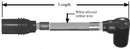
| 178-6084 SID Series Double Ended Hybrid Cable Assembly Wire Dia. 0.165 (4.1)
178-6083 SID Series Double Ended Hybrid Cable Assembly Wire Dia. 0.180 (4.5)
Mating connector: All SID receptacles Mating method: Push-on/Pull-off |
Download this page as a PDF for best print quality.
SID Push-on/Pull-off cable assemblies and receptacles, Page 2 
SID - 15 KVDC Receptacles | |
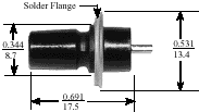
| | P/N 26RC1031 SID Series Male Solder Flanged Receptacle (Male Contact) Solder-Flanged Receptacle 15 KVDC
- Mounting: Solder flange
- Terminal type: Exposed solder tube
- Body Material: Molded Plastic
- Mating connectors: Mates all SID cable assemblies
- Maximum Leakage: 1 x 10⁻⁶ cc/sec. He
| 
| | P/N 60RC1031 SID Series Male Flanged Jam Nut Receptacle (Male Contact) Flanged Jam Nut Receptacle 15 KVDC
- Mounting: Jam nut flange
- Terminal type: Exposed solder tube
- Body Material: Molded Plastic
- Mating connectors: Mates all SID cable assemblies
- Seals: “O” ring flange seal
- Maximum Leakage: 1 x 10⁻⁶ cc/sec. He | 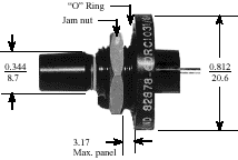
| | P/N 29RC1031 SID Series Male Plastic Flanged Receptacle (Male Contact) Plastic-Flanged Receptacle 15 KVDC
- Mounting: Designed for encapsulation or bonding
- Terminal type: Flush to recessed solder tube
- Body Material: Molded Plastic
- Mating connectors: Mates all SID cable assemblies | 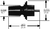
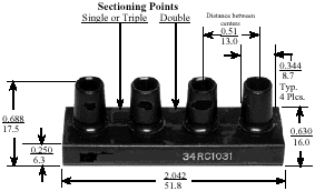
| | P/N 34RC1031 SID Series Male Plastic 4 Receptacle Block (Male Contact, 4 places) Plastic 4-Receptacle Block 15 KVDC (each)
- Mounting: Designed for encapsulation or bonding
- Terminal type: Flush solder tube (4 places)
- Body Material: Molded Plastic
- Mating connectors: Mates all SID cable assemblies
- Seals: None
- Note Block can be precision cut by customer to convert to single, double or triple connector
| 
|
Download this page as a PDF for best print quality.
Index by Part Number

AWG wire data
 | AWG | STRANDING | APPROX. DIA. | CROSS SECTION | DC RESISTANCE | CURRENT RATING | | MM | INCHES | OHMS/1000M | (amps) Free air. 80°C* | | 30 | 41/46 | 0.3 | 0.012 | 0.051 | 337.3 | 0.4 | | 29 | 51/46 | 0.35 | 0.014 | 0.064 | 271.3 | 0.5 | | 28 | 41/44 | 0.37 | 0.015 | 0.081 | 212.3 | 0.6 | | 26 | SOLID | 0.4 | 0.016 | 0.13 | 133.9 | 1 | | 26 | 11139 | 0.48 | 0.019 | 0.141 | 122.4 | 1 | | 26 | 11962 | 0.51 | 0.02 | 0.127 | 136.2 | 1 | | 26 | 19/38 | 0.5 | 0.02 | 0.151 | 113.8 | 1 | | 26 | 51/42 | 0.56 | 0.022 | 0.16 | 107.3 | 1 | | 26 | 66/44 | 0.48 | 0.019 | 0.131 | 131.9 | 1 | | 24 | SOLID | 0.51 | 0.02 | 0.205 | 84.3 | 1.6 | | 24 | 10409 | 0.61 | 0.024 | 0.224 | 76.8 | 1.6 | | 24 | 11231 | 0.64 | 0.025 | 0.201 | 85.6 | 1.6 | | 24 | 16/36 | 0.61 | 0.024 | 0.203 | 85 | 1.6 | | 24 | 19/36 | 0.64 | 0.025 | 0.241 | 71.5 | 1.6 | | 24 | 41/40 | 0.59 | 0.023 | 0.205 | 84 | 1.6 | | 22 | SOLID | 0.64 | 0.025 | 0.326 | 52.8 | 2.5 | | 22 | 34909 | 0.76 | 0.03 | 0.356 | 48.2 | 2.5 | | 22 | 19/34 | 0.8 | 0.032 | 0.383 | 44.9 | 2.5 | | 22 | 26/36 | 0.75 | 0.03 | 0.329 | 52.5 | 2.5 | | 22 | 65/40 | 0.78 | 0.031 | 0.326 | 52.5 | 2.5 | | 20 | SOLID | 0.81 | 0.032 | 0.518 | 33.5 | 4 | | 20 | 34907 | 0.96 | 0.038 | 0.567 | 30.5 | 4 | | 20 | 35001 | 1.02 | 0.04 | 0.509 | 33.8 | 4 | | 20 | 19/32 | 1.01 | 0.04 | 0.609 | 28.2 | 4 | | 20 | 26/34 | 0.94 | 0.037 | 0.524 | 32.8 | 4 | | 20 | 105/40 | 0.99 | 0.039 | 0.526 | 32.8 | 4 | | 18 | SOLID | 1.02 | 0.04 | 0.823 | 21 | 8 | | 18 | 34905 | 1.21 | 0.048 | 0.901 | 19 | 8 | | 18 | 16/30 | 1.23 | 0.048 | 0.815 | 21 | 8 | | 18 | 19/30 | 1.27 | 0.05 | 0.968 | 17.7 | 8 | | 18 | 41/34 | 1.19 | 0.047 | 0.826 | 21 | 8 | | 18 | 65/36 | 1.25 | 0.049 | 0.823 | 21 | 8 | | 18 | 168/40 | 1.34 | 0.053 | 0.842 | 20.3 | 8 | | 16 | SOLID | 1.29 | 0.051 | 1.309 | 13.1 | 10 | | 16 | 34903 | 1.53 | 0.06 | 1.433 | 12.1 | 10 | | 16 | 19/29 | 1.43 | 0.056 | 1.22 | 14.1 | 10 | | 16 | 26/30 | 1.5 | 0.059 | 1.324 | 13.1 | 10 | | 16 | 41/32 | 1.5 | 0.059 | 1.326 | 13.3 | 10 | | 16 | 65/34 | 1.57 | 0.062 | 1.309 | 13.1 | 10 | | 16 | 260/40 | 1.73 | 0.068 | 1.303 | 13.1 | 10 | | 14 | SOLID | 1.63 | 0.064 | 2.081 | 8.2 | 15 | | 14 | 34901 | 1.85 | 0.073 | 2.285 | 7.6 | 15 | | 14 | 19/27 | 1.8 | 0.071 | 1.94 | 8.9 | 15 | | 14 | 41/30 | 1.89 | 0.075 | 2.088 | 8.2 | 15 | | 12 | 34899 | 2.44 | 0.096 | 3.66 | 4.9 | 20 | | 12 | 19/25 | 2.27 | 0.09 | 3.085 | 5.6 | 20 |
Download this page as a PDF for best print quality.
Application guide for product selection
Criterion | Guide | Voltage Rating | Reynolds rates voltage as the “maximum operating voltage.” Ratings are for steady state DC The user should define the maximum DC voltage of the proposed circuit and select a connector rated at least 25% above the maximum circuit operating voltage. If the circuit contains voltage with an AC component or is pulsed DC, the user should consult with Reynolds engineering department before choosing a connector. | Altitude Operation | If a proposed application involves operation at a reduced pressure equivalent to 15,000 ft. or higher, the user should refer to p. 42 for background on the relationship of voltage stand off and atmospheric pressure. Connectors presented in this catalog are clearly rated concerning operation at altitude. Reynolds altitude-rated connectors use precision elastomeric seals
to effect an altitude seal and requires no silicone grease to operate reliably at their rated voltage.
| Operating Temperature | The user should accurately establish the operating temperature range of any application for high voltage connectors. This
is very important for sea level applications and becomes critical for altitude operation. The user should be realistic in evaluating the temperature range. Connectors designed to operate over a range of -55°C to +125°C are considerably more expensive than those designed for room ambient operation or even -40°C to +70°C. The operating temperature is clearly indicated for all connectors in this catalog. | Plugs | Plugs, the ends that are attached to cable assemblies, are available in some cases as a bag assembly for installation by the user. Reynolds generally discourages the purchase and installation of these connectors by the user, especially if the final assembly is to be used at altitude and/or extremely cold temperature, for several reasons. (1) Extreme cleanliness must be observed to preclude conductive contamination. (2) If the connector requires bonding (most do), only an experienced person with all the necessary potting room equipment should attempt the installation. (3) Assemblies must be voltage–stress tested and, when destined for use at altitude, in an altitude chamber capable of simulating the equivalent of 70,000 ft.
| Receptacles | Receptacles also must be kept clean, particularly in the interface area. If the rear portion of the receptacle requires encapsulation, it is best to have this done and tested by Reynolds prior to shipment. However, the potting of a receptacle
is usually straightforward and can be accomplished by following the material manufacturer’s printed instructions. | Wire and Cable | There is no single wire or cable suitable for all applications and conditions. Following are comparisons:
FEP Advantages: | Silicone Rubber Advantages: | High dielectric | Fair dielectric strength | Abrasion resistant | Good flexibility | Good corona characteristics | Easy to bond and encapsulate with silicone rubber | Can be etched and silicone–rubber coated | Disadvantages: | Resistant to most fluids including Coolanol™ | Relatively large diameter compared to FEP | Disadvantages: | Susceptible to pinholes and wire migration | Must be etched for bonding or encapsulation | Incompatible with Coolanol™ and some other oil dielectrics |
| FEP Wire & Cable Etching -Coating | FEP wire can be etched and coated with silicone rubber for encapsulation using silicone rubber compounds or bonding to molded silicone rubber components using approved elastomeric bonding materials. FEP wire that has been etched but not coated can also be used for encapsulation or bonding to most epoxy materials. These processes give FEP wire a versatility found in no other high voltage wire or cable and make it an excellent choice for most high voltage applications | Cable Routing and Bend Radius | In routing cable, the user should take care to avoid making sharp bends. Sharp bends put added stress on the wire strands and can create a corona stress point. Sharp or rough metal edges in the routing area should also be eliminated, especially when using silicone cable. Torquing a cable excessively during routing should be avoided. | Liquid Dielectrics | Reynolds connectors use silicone rubber seals and “O” rings to effect dielectric and pressure sealing. Silicone rubber, including silicone rubber cable, is incompatible with many dielectric oils and Coolanol™ dielectric. While these are excellent dielectric mediums they can cause silicone rubber to swell. Some Reynolds connectors offer fluorsilicone seals and/or insulators for use with these dielectrics. Only FEP or PFA cable should be used where these dielectrics are present. | Loss Line Cable | Reynolds manufactures a complete line of high voltage loss line or distributed loss R.F. attenuation cable. The user requiring R.F. attenuation should consider using loss line. Reynolds engineers are available for application consultation. | Corona | Users with concerns about corona should consult Reynolds engineering department before making a high voltage connector choice. Reynolds is extremely knowledgeable concerning the origins of corona and its effects and and possible remedies. Reynolds makes no claim to manufacturing “corona-free” connectors, cable or cable assemblies. Reynolds does, however, maintain extensive corona research and test data on its products with the objective of manufacturing connectors as resistant to the effects of corona as possible. Reynolds is noted in the industry for its corona detection equipment and technical competence to analyze the existence and level of corona in a connector or circuit. |
Download this page as a PDF for best print quality.
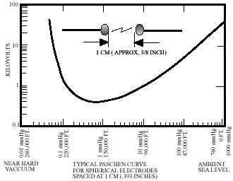
Paschen curve: Voltage arc level vs atmospheric pressure
| Paschen’s results
In the 19th century, Paschen, a German scientist, conducted experiments to determine electrical arc char-acteristics when ambient pressure changed. He spaced two spherical electrodes at a constant 3/8 inch (1cm). He then reduced the ambient pressure in increments from sea level (760 mm Hg.) to 260,000 ft. (0.01 mmHg.). At each selected pressure increment he increased the voltage across the electrodes until a low-energy arc occurred.
The curve on the chart above tells the story. At sea level, about 30,000 VDC is required to initiate an arc across the electrode gap. At 47,000 ft. the arc level drops to about 1200 VDC. Accordingly, the worst altitude is 150,000 ft., where only about 300 VDC will arc across the electrodes. Electronic Countermeasure Systems (ECM) and other radar and electronic systems aboard aircraft require high voltage connectors and cable assemblies to function at altitudes up to 70,000 ft. with 1,500 to 40,000 volts applied. Missile-borne ECM systems raise the requirement to 150,000 ft..
The problem
In low voltage electrical connector applications (less than 500 volts DC), reduced air pressure presents little concern or special design considerations. But to take one example, a high voltage connector operating requirement of 10,000 volts DC, the creep path (arc distance) between two conductors at sea level would be 1/2 inch (12.7mm), and at 70,000 ft. it would be 5 inches (127mm) minimum.
The extended creep path solution
If no design solution were possible other than the lengthening of the creep path, then aerospace high voltage connectors would occupy unreasonable volume and would be extremely heavy.
Elastomer seals
To eliminate the need for a lengthened creep path, all connectors manufactured by Reynolds that are rated for altitude operation have precision elastomer seals incorporated into the design. These seals block high voltage creep at reduced air pressure.
Temperature swing effect
Temperature swings from -55°C to +125°C can cause elastomer materials to exhibit compression set or loss of memory between hot and cold cycles. This can result in voltage creep past the seals and subsequent failure of the connector. Through the use of select elastomer materials and seal geometry, Reynolds altitude rated connectors will operate reliably when exposed to reduced pressure and hot and cold cycling.
|
Download this page as a PDF for best print quality. |

