|


| |
Click here to see ISO 9001:2008 Certificate
Click here to see how Teledyne Reynolds can do your High Voltage Assembly, Potting & Testing for you
DEFINITION OF GAS DISCHARGE TUBE TERMS: | D.C. BREAKDOWN:
The voltage at which the initial discharge occurs with a slowly rising voltage applied across the electrodes of the tube. (The test voltage is applied at 100 volts per second or less).
IMPULSE BREAKDOWN:
The voltage at which the initial discharge occurs with a rapidly rising voltage applied across the electrodes of the tube. This breakdown voltage is a function of the rate of rise of the applied voltage and is generally stated for a particular ramp voltage.
SURGE CURRENT:
The surge current capability of a spark gap is a function of the waveshape of the surge and of the tube design. Each spark gap design has its own inherent maximum surge current capability for a given surge waveshape. Factors such as tube and electrode size, gas fill, and gas pressure determine the tube capability.
INSULATION RESISTANCE:
The insulation resistance between electrodes of a spark gap is normally measured at 100 volts DC when the | spark gap is in a non-ionized condition. As the device is used this insulation resistance decreases and normally end of life is determined when this resistance reaches a selected value.
LIGHTNING STROKE CURRENTS:
In selecting a particular spark gap for a lightning protection application, the magnitude of the stroke current must be predicted. Lightning stroke peak currents vary greatly from several hundred to several hundred thousand amperes depending on the particular stroke and whether it is induced into the equipment being protected or arrives as a direct stroke through an electrical conductor.
EMP or ELECTROMAGNETIC PULSE:
The electromagnetic radiation associated with a ther- monuclear explosion and the electrical transient coupled into circuitry due to this radiation.
GLOW REGION:
The first significant current that flows following in initiation of an overvoltage condition. |
Introduction | ABOUT REYNOLDS: | Reynolds Industries was founded in 1948 and has grown to be one of the largest privately held non-conglomerate companies specializing in the design and manufacture of electrical connectors. In addition to electrical connectors, Reynolds manufactures spark gaps (spark gaps), transient protection products, exploding bridgewire and exploding foil ordnance, related electronic firing systems, and high voltage/high energy density capacitors. Our facilities in Marina del Rey, California, near the Los Angeles airport, house our General Offices as well as the Connector Products Division and the Electro-Ceramic products Division.. This 100,000 square foot facility is fully air conditioned creating a white room atmosphere to provide the ultimate in quality products and manufacturing control.
A separate facility in northern California, accommodates our ordnance subsidiary , RISI.
The Electronic Products Division, located in Santa Maria, California, midway between San Francisco and Los Angeles has capabilities for the design, development and manufacture of high voltage/high energy density capacitors, voltage multiplier products, spark gaps (spark gaps) and transient protection devices.
Reynolds also has manufacturing facilities in the United Kingdom and Switzerland and sales offices in France and Sweden. |
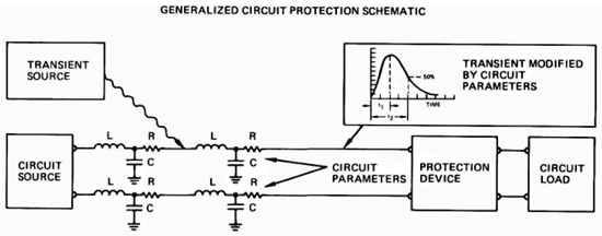
Spark Gaps Application Information Spark Gaps are basically high energy voltage controlled switching devices. They are unique in their ability to repeatedly switch currents of thousands of amperes, which leads to their most common usage as transient protectors for applications where high energy transient electrical surges are anticipated.
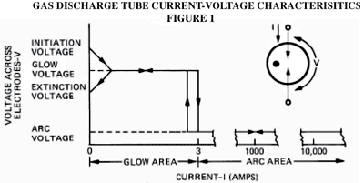
The basic design and operation of a spark gap spark gap is simple. If two metal electrodes are separated by a suitable insulator and a gas placed between the electrodes at a | specific pressure, an electrical breakdown occurs between the electrodes following the application of sufficient voltage across the electrodes. Once formed, this electrical arc is capable of carrying currents of many thousands of amperes while the voltage developed between the electrodes during the arc state remains relatively independent of this arc current. Typically this arc related voltage is in the range of twenty to thirty volts once the breakdown has been initiated. | | To initiate the arc in a spark gap, a voltage considerably higher than the arc voltage must be applied. Figure I illustrates the current-voltage characteristic of a typical spark gap.
As a voltage is applied across the electrodes of the tube this voltage must be raised until it reaches the initiation point before current begins to flow. This initiation voltage is both a function of the device design and the rate at which the input voltage is applied. Characteristically spark gaps require higher initiation voltages the more rapidly the input voltage is applied. The first current that flows following initiation is the glow current. Over a narrow band of low amperage currents an associated glow voltage occurs across the electrodes which is essentially independent of current. This low amperage area is called the glow region and it is the normal operational region of the voltage regulator type of spark gap.
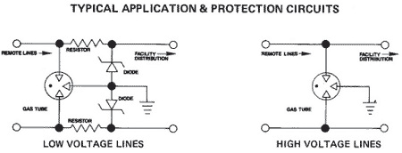
Most spark gap protection devices are not designed for operation in this glow region due to the current limitations of the region, but are intended for use in the arc area which occurs as current is provided beyond the glow region.In the application of spark gap spark gaps, two fundamentals from Figure I are of importance. First, the applied voltage must reach the initiation voltage before breakdown can occur and second, in order for the arc to extinguish following the initiation of the breakdown, the voltage curve must be retraced back through the glow area. | Figure IL-A shows a basic application for a spark gap used as a protective device. The spark gap is placed across the input terminals of the circuit load to be protected. Because of its high inherent impedance the spark gap is essentially undetected by the normal signal voltages, however with the arrival of a transient voltage of sufficient magnitude the spark gap goes into its arc state, thus placing a very low impedance across the load for the duration of the transient.
Figure lI-B illustrates the same basic application except for a three electrode spark gap on a balanced pair line. It is apparent from the current-voltage characteristics of Figure I that a breakdown or initiation voltage selected for the spark gap must be above the normal signal voltage to prevent unwanted breakdown of the protector. In addition, if the incoming lines include a D.C. voltage, consideration must be given to the current-voltage requirements of the spark gap to allow it to extinguish following initiation of the tube by a transient voltage. Extinction of the are where the source is an AC voltage is relatively direct due to the zero voltage crossover point which occurs with each polarity reversal.
For all but simple communication and data lines, application of spark gaps involves the combination of the spark gap with other circuit devices to fulfill the requirements of the current-voltage relations of the spark gap. For all applications, selection of a spark gap device with the proper current capacity, coordinated with the expected transient, is required. |
| Examples of the combination of spark gaps with other circuit devices are as follows. These coordinated circuit protectors are hybrids and may be specified and packaged as a complete system.
For D.C. systems whose normal voltage and power supply short circuit current are adequate to hold the spark gap in the arc or glow area, a series resistance must be provided with the spark gap. Either a resistor having a high current capability or a varistor may be used. The resistance element must drop | sufficient system voltage to bring the across -the -electrode voltage below the glow voltage curve for the spark gap once the transient voltage has passed. Several resistance-spark gap combinations may be placed in parallel to lower the transient
voltage developed across the resistance elements.
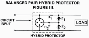
For AC systems with a large source power capability, a resistance element may be placed in series with the spark gap to lessen the current duty required of the spark gap until the next current zero is reached and extinction occurs. | 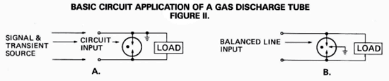 | For solid state systems having a low voltage damage threshold, a second stage of protection using a device whose current capability is less than the spark gap, but which has a lower initiation voltage may be used. An example of such a device is the hybrid combination of a zener diode and a spark gap shown in Figure III for a balanced pair line.
The resistances, R1 ad R2, limit the current through each | zener diode until the spark gap discharges. There are many combinations of circuit elements which may be used with the spark gaps for specific applications.
Reynolds Industries offers the assistance of their Application Engineering Group to provide technical help with specific applications. Complete hybrid packages designed specifically for your application can also be supplied.
| |
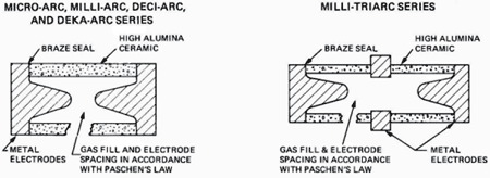
Construction and Typical Application Circuits | Each spark gap features ceramic to metal construction providing a rugged package capable of withstanding the most severe vibration and shock environments. A high temperature braze seal provides a reliable gas seal throughout temperature extremes. | |
TYPICAL CIRCUITS: | | 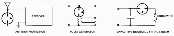 | 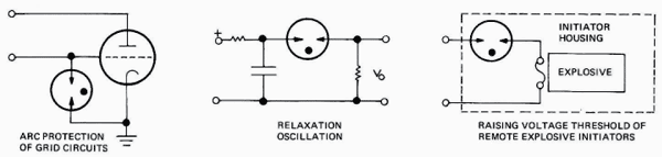 |
Selecting a spark gap Selecting the proper spark gap for a particular application involves the simultaneous consideration of several factors. These considerations lead to a spark gap choice which: will be most economical will have the ability to provide circuit protection for all expected transients, and will not interfere with normal circuit operation either before or after the transient event.
This section provides a checklist for selecting a spark gap for communication circuitsand also AC and DC power circuits.
A. COMMUNICATION CIRCUIT APPLICATIONS
Selection of a spark gap for application on communication circuits is perhaps the easiest of the three basic application problems. Most communications applications do not require any special consideration of circuit effects on the spark gap after the transient has passed because these applications normally do not have the ability to hold the spark gap in either the glow or arc region after the transient surge has passed.
Communications spark gap selection involves the following five steps:
Determine or estimate the transient current waveshapes and voltage risetimes at its source. Determine or estimate the transient current waveshape and voltage risetime at the point in the circuit where the protection will be installed. This step is necessary as often as the inherent circuit parameters, such as conductor size, will become the limiting factor determining surge current magnitude at the spark gap installation location. This step will consequently prevent over specifying the spark gap current requirement. Based on the transient current requirements of the spark gap determined in steps 1 and 2, select a spark gap size from the catalog data sheets which is compatible with this surge requirement. From the data sheet for the chosen spark gap size, select an individual tube which has the lowest DC breakdown possible but which will not discharge or initiate under normal system break voltages. A minimum DC breakdown at least 20% above the system peak voltage is advised. Following the selection of the individual spark gap, determine its impulse breakdown characteristics from the data sheet specifications for the device. This value may be compared with the transient voltage determined in steps 1 and 2 and an estimate made of the peak short term voltage to which the protected circuit will be exposed following installation of the spark gap. In the event this short term voltage exceeds the required protection level, a hybrid type of protection device should be considered.
B. AC POWER CIRCUIT APPLICATIONS
The method of selection of a spark gap for AC power applications is identical to that used for communications circuits except for one important difference. When the power source can supply sufficient short circuit current for one half cycle, this current and its duration must be added to the transient current waveshape in determining the duty cycle required of the spark gap. This is because the spark gap, once initiated by the transient, must carry the power source current for the remainder of that half cycle until the tube extinguishes on the next power frequency current zero. This power supply portion of the duty cycle required of the spark gap is called the ìpower follow currentî. Its amplitude is not normally significant in relation to the transient surge amplitude but at power frequencies its duration is quite long.
Often in AC power applications, to permit the use of a spark gap of practical size, a small resistance (less than one ohm) or varistor is placed in series with spark gap to limit this power follow current. This resistance develops a voltage, known as the ìdischarge voltageî which is due to the transient surge current. This discharge voltage appears across the protected load and must be considered in determining the protection level achieved.
A checklist for AC power circuits applications is as follows: Determine or estimate the transient current waveshape and voltage risetime at its source. Determine or estimate the transient current waveshape and voltage risetime at the point in the circuit where the protection will be installed. Consider the limiting effects of the circuit parameters on the transient between the point the transient is introduced into the circuit and the point where the protector will be installed. To the transient waveshape determined in step 2, add the half cycle power current of the source. From this combined current waveshape select a spark gap from the catalog data sheets which will provide the necessary surge duty requirement or, as will be the usual case, consider the addition of a series resistance device to a spark gap which will bring its surge current duty within the capability of an existing device. Reynolds Application Engineering Group is available to assist with this selection if desired. Once a spark gap size and resistance combination (if required) has been selected, select a particular device from the chosen data sheets which will provide a DC breakdown at least twenty percent above the normal system AC peak voltage. Following selection of the individual spark gap, determine its pulse breakdown characteristics from the data sheet specifications for the device. In addition, if a series resistance has been added, determine the discharge voltage across this resistance due to the transient surge current. Combining these two voltages, the short-term impulse breakdown voltage of the spark gap and the discharge voltage of the resistance element, provides the transient exposure voltage of the protected load. As with the communication circuit application, in the event this exposure voltage is in excess of the desired protection level of the load, additional hybrid combinations must be considered.
C. DC CIRCUIT APPLICATIONS
Application of spark gaps on DC circuits provide the most challenging applications because of the inherent characteristics of spark gaps to continue to discharge as long as an arc or glow current can be provided. From the general Applications Information of pages 3 and 4 we see that unless the DC supply voltage across the spark gap is reduced to a level lower than the current-voltage relationship for the tube for a given source current, the spark gap will continue to conduct following its initiation by a transient surge. For this reason, for other than low source current DC applications and DC system supply voltages less than the arc voltage of the tube, we must supply supplemental circuit elements to assure that the spark gap will extinguish. Circuits with DC supply voltages below the arc voltage of the spark gap, or with low source currents and voltages below the glow voltage of the tube may be treated as communications circuits.
For DC circuits, which cannot be treated as communications circuits, the following checklist is provided: Determine or estimate the transient current waveshape and voltage risetime at its source. Determine or estimate the transient current waveshape and voltage risetime at the point in the circuit where the protector will be installed. Consider the limiting effects of the circuit parameters on the transient between the point where the transient is introduced into the circuit and the point where the protector will be installed. Based on the transient current requirements of the spark gap determined in steps 1 and 2, select a spark gap size from the catalog data sheets which is compatible with this surge current requirement. From the data sheet for the chosen spark gap size, select an individual tube that has the lowest DC breakdown at least twenty percent higher than the DC voltage.
If the system DC voltage is higher than 100 volts the Reynolds Applications Engineering Group should be consulted due to the possibility of exceeding the glow voltage of the particular spark gap.
Once a spark gap has been selected, provisions must be made to include supplemental circuit resistance to limit the DC system current through the spark gap to a value which will bring the tube back into the glow region following the passage of the surge. If this added resistance can be placed in series with the normal system load carrying conductors the transient voltage developed across the resistor will not appear across the protected load. If this added resistance must be placed directly in series with the spark gap it will also develop a discharge voltage similar to that found in the AC power circuit application of spark gaps, which will appear across the protected load. | |
Because of the critical nature of these extinguishing criteria in the DC circuit applications, it is often helpful to check for extinction of the spark gap in a laboratory test circuit.
If extinction of the spark gap remains a problem, often tubes may be placed in series to aid tube turn off. In addition, several resistance-spark gap combinations may be placed in parallel to lower the overall discharge voltage seen by the protected load. If desired, the Reynolds Applications Engineering Group will assist with these combinations.
| |
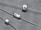
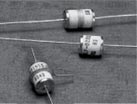
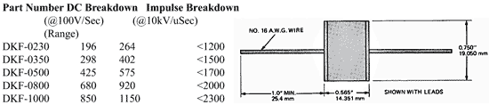
Ordering Information | | | FROM TOP: MLH, MCF, MCH | FROM TOP: MLH-2S, MLF, MLT | FROM TOP: DKF, DCF |
spark gap ORDERING INFORMATION
Any of the five families of standard spark gaps specified in this literature may be purchased through the Reynolds Sales Department by using the following part number system.
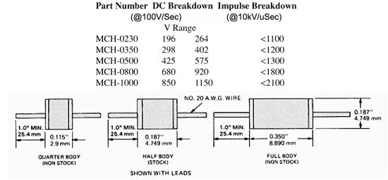
Each part number is described by an eight-character system. The first three characters in the part number are alpha characters describing the family size. The following four numeric number characters designate the desired DC breakdown, if leads are desired, an alpha ìLî is added to the completed part number. Rated DC breakdowns are +/- 15%. | FAMILY -
MICRO-ARC -
MILLI-ARC -
MILLI-TRIARC -
DECI-ARC -
DEKA-ARC -
| DESIGNATOR
MCF = FULL; MCH = HALF; MCQ = QUARTER;
MLF = FULL; MLH = HALF;
MLT
DCF
DKF | | Example: 230 volt mull-arc, full size P/N MLF-O23O, P/N (with leads) MLF-O23OL |
RADIOACTIVE BACKFILL GAS
All standard except 90 volt versions, Reynolds spark gaps contain minute amounts of Tritium Backfill Gas.(Maximum amount 10 microcuries). Each spark gap is identified with international radiation symbol H
MICRO-ARC SERIES
The Micro-Arc spark gap series are designed for electrical transient protection and energy release in applications where miniaturized packaging is necessary and small transient currents are anticipated. They may also be used where a large one time energy release is required, for example, in the initiation of explosive detonations. They offer a high insulation resistance of greater than 1 x 10E9 ohms and capacitance of less than 1pF. Surge capability is 1000 amperes (8 x 20 usec waveshape).
The spark gaps are available in a DC breakdown voltage range from 90 to 2000 volts except for the half and quarter sizes which are limited to an upper limit of 1000 and 500 volts respectively. Note: Voltages are available thru 1650V on MCQ and thru 2000V on MCH series provided adequate over-potting is utilized by the customer. Units normally stocked are as follows. Other breakdown voltages are available on request. | |
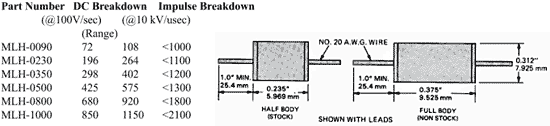
MILLI-ARC SERIES
The convenient physical size of the Milli-Arc series of spark gaps and their 10,000 ampere (8 x 20 usec waveshape) discharge capability make this series the most suitable for general purpose transient protection. They also may be used for energy release in exploding bridgewire applications and in various vacuum tube grid circuits for tube arc protection. Insulation resistance is greater than 109ohms and capacitance is less than 2 pF. Milli-Arc tubes are available in breakdown voltages from 90 to 4500 volts (MLH), 8500 volts (MLF). Units normally stocked are as follows. Other breakdown voltages available on request. | |
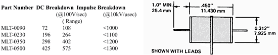
MILLI-TRIARC SERIES
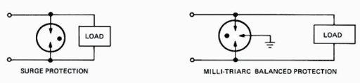
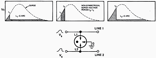
Milli-Triarc spark gaps are designed for electrical transient protection of balanced pair communications lines. Their three-electrode design provides a discharge path from each line to ground in addition to a line-to-line path for metallic surges. They may also be used for triggered applications where an adequate trigger pulse is available.
When installed on balanced pair lines, where symmetrical surge voltages are anticipated on each line pair, this three electrode series provides for a rapid sympathetic breakdown of the opposite line electrode to ground following the initial line to ground breakdown. The delay, t2-tl shown in the diagram below, is considerably shorter with this series of spark gaps than that found where two separate two electrode spark gaps are used. The milli-triarc type tube also provides line-to-line surge protection. These tubes are capable of a 10,000 ampere (8 x 20 usec waveshape) surge. Insulation resistance is greater than 1 x 10E9 ohms. Capacitance is less than 2 pF.
Normally, stocked units are as follows. Other breakdown voltages to 2000 volts are available on request. | | |
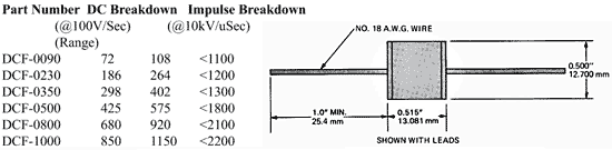
DECI-ARC SERIES
The Deci-Arc tubes are for protection in circuits where high energy transients are anticipated and where size 18 AWG or larger wire sizes are used. They have a 20,000 ampere (8 x 20 usec waveshape) capability and may be used in combination with suitable series resistance for protection on both AC and DC power circuits. Capacitance of these tubes is less than 10pF and initial insulation resistance is greater than 10 ohms.
The spark gaps are available in DC breakdown voltage ranges from 230 to 10,000 volts. Units normally stocked are as follows. Other breakdown voltages available on request. | |
DEKA-ARC SERIES
The Deka-Arc series of spark gaps is designed for heavy duty electrical transient protection. Their 40,000 ampere (8 x 20 usec waveshape) capability makes them suitable for many direct lightning stroke protection applications and for power line protection when used with appropriate series resistances. They may also be used in circuits where long life is desired under repetitive pulse conditions. Capacitance of these tubes is less than 10 pF and initial insulation resistance is greater than 1 x 10E9 ohms. Tubes are available in DC breakdown voltage ranges from 230 to 10,000 volts. Units normally stocked are as follows, other voltages available on request. | |
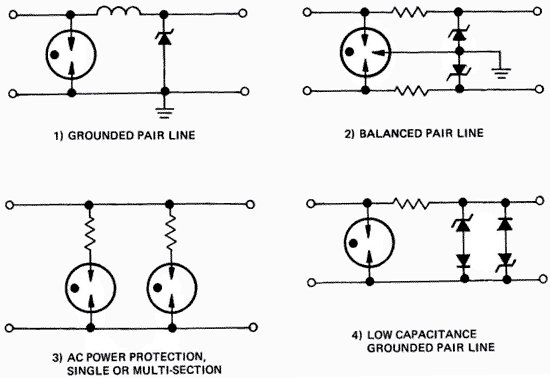
Hybrid Protection Systems Gas tubes may be combined with common circuit devices to form hybrid protection systems having protection characteristics superior to those of the individual components on their own. Typical supplemental devices used are resistors, diodes, inductors, capacitors, and varistors.
Four typical circuits are illustrated below. In circuit 1) the inductor develops a voltage from the transient surge current thus permitting the spark gap to reach its impulse breakdown voltage. The diode clips any overshoot voltage at the circuit output, diode destruction is prevented upon breakdown of the spark gap. Circuit 2) illustrates a similar application for a balanced pair line using the three electrode triarc type spark gap. Circuit 3) utilizes series resistances to limit power following in AC power applications. Several spark gap-resistor combinations may be paralleled to increase the system surge current capability without increasing the surge caused by Ohms Law voltage drop developed across the circuit.
A high frequency communication circuit protection system is illustrated in circuit 4. This circuit, similar to circuit 1, has low capacitance diodes placed in series with the avalanche diodes to reduce circuit capacitance to less than 200 pF.
Reynolds offers a variety of hybrid protection systems designed and tested to individual customer applications. This design task often includes the mechanical packaging interface between the transient source environment and the userís equipment. Several protection systems manufactured and designed by Reynolds are illustrated on the following pages.
| |
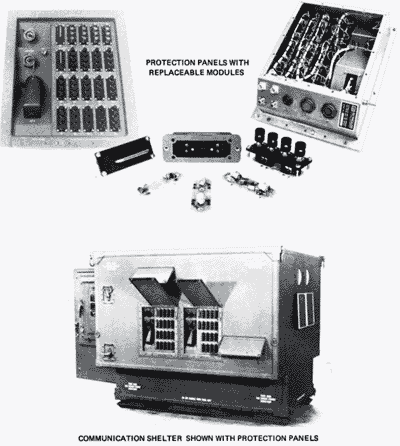
DESCRIPTION:
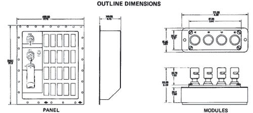
Designed to provide lightning and EMP (electromagnetic pulse) protection for a mobile communication shelter, this input panel features replaceable modules containing hybrid spark gap protection circuits.
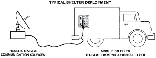
Incoming communication circuits route through the panel, which is mounted on the side of a shelter. Modules containing the individual protection circuits are designed for the electrical characteristics of the incoming lines. Each module plugs into a receptacle in the panel that is then wired through connectors to the shelters electronic circuit loads. Field wire carrying data and communication information from remote sources is rapidly terminated at the shelter with push to insert receptacles located on the external face of each module. | |
This panel illustrates the combination of transient protection circuits and specialized packaging design to provide an over-voltage protection system suitable for commercial and military applications. Reynolds offers this capability for a comprehensive solution for all communication and power transient protection requirements. | | | |
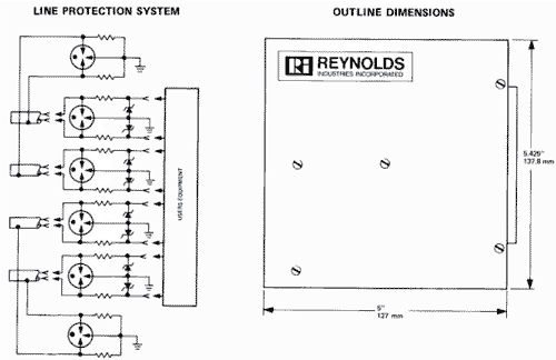
This high-density hybrid protection package is designed for card mounting of multiple circuit boards to provide induced lightning surge protection. A typical application is for a communications facility having many shielded input line pairs. Provisions are included for surge diversion from non-grounded cable shields (screens). Each protection package contains both input and output connectors permitting rapid field replacement. Induced surges to 2500 amps are possible without system damage. Output lines contain avalanche diodes to limit surge caused output voltages to less than 50 volts.
| | |
In-series Gas Discharge Because of their very low capacitance, low on state impedance and fast response to voltage transients, sealed spark gaps frequently provide the best protection against destructive vacuum tube inter-grid breakdowns. They are frequently not used however, because tube bias voltages and source impedances prevent the protective spark gap from extinguishing following the shunting of an inter-grid surge current. This application problem can usually be avoided by the use of two or more spark gap fabricated in series by Reynolds.
Spark gap have two distinct on states. The first is a high voltage, low current state known as the glow state. Typically, discharge tubes may be held in this state following breakdown if the supply voltage has sufficient source impedance to limit the tube current to the high milliampere range. This glow state may be maintained as long as the supply voltage is held above the inherent glow voltage of the tube (typically 180 volts) and the tube is supplied with sufficient current to maintain the glow, but not enough current to permit it to enter its second type of on state.
The second on stage is a low voltage, high current condition and is the state the tube enters when conducting large transient surge currents.
In high grid bias voltage problem applications, where a single spark gap is installed, the protecting tube responds to an inter-grid discharge and diverts the surge in its low voltage, high current arc state. Following the passage of the surge the spark gap is unable to extinguish because the grid bias power source has sufficient voltage and supply current to hold the tube in its glow state. For many grid voltage ranges that are too high for the application of a single spark gap, two or more protection tubes may be installed in series. In this arrangement, their glow voltages are additive, thus the series string will extinguish bias voltages two or more times the extinguishing voltage for a single discharge tube.
Reynolds provides a number of these in series combinations of ceramic to metal constructed, spark gaps brazed together with customer specified lead or threaded stud terminals. These tubes are capable of extinguishing low current source bias voltages up to 450 volts D.C. and high frequency A.C. voltages of several thousand volts. Where specific applications require circuit testing to provide a solution to this extinguishing problem, Reynolds is always pleased to work with the user towards a solution. Below are examples of typical in series spark gap specifications. | |
Transient Limiters Reynolds offers a variety of coaxial and multiple pair transient limiters. Each is designed to provide lightning protection to the individual customerís requirements. The coaxial transient limiters can be designed using a variety of connectors. Circuits are available using spark gaps or hybrid circuits. Should circuit requirements change, component parts can easily be changed.
The multiple pair transient limiters can be designed for use with grounded pair or balanced pair lines. They also feature hybrid circuitry where required by the application. | |
|


.gif)

.gif)
